A Minimal 8051 Microcontroller Setup
Written by Stefan Paul Noack CC-BY-4.0
Introduction
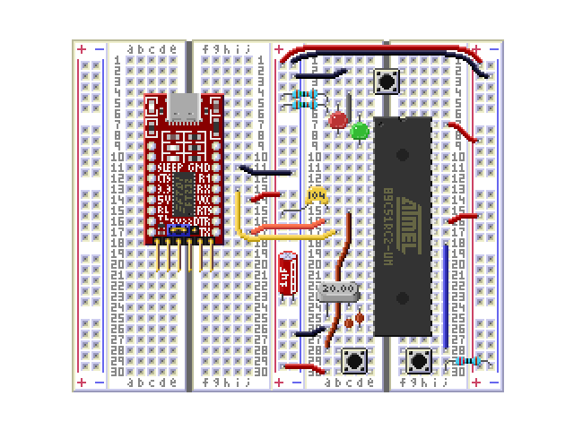
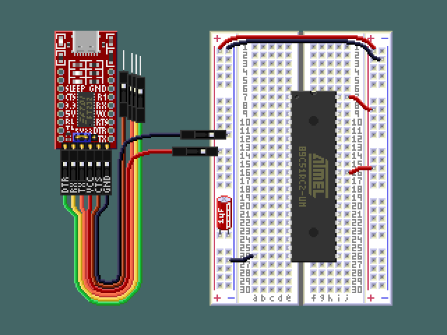
In this article, we will use the AT89C51RC2 microcontroller with a minimal set of external parts to make it do something interesting. This model has been specifically chosen because it comes with a serial bootloader, which allows us to program it without a special programming device. All that is needed is a USB to UART adapter, which will also provide power to the circuit via the USB port, a quartz crystal for the system clock, and some buttons and LEDs for input and output, as well as a few passive components and wires. The entire thing can be put together on a solderless breadboard. No special software is required. The machine code will be manually assembled and then loaded onto the device using a Web Serial terminal available directly on this website.
Building the Circuit
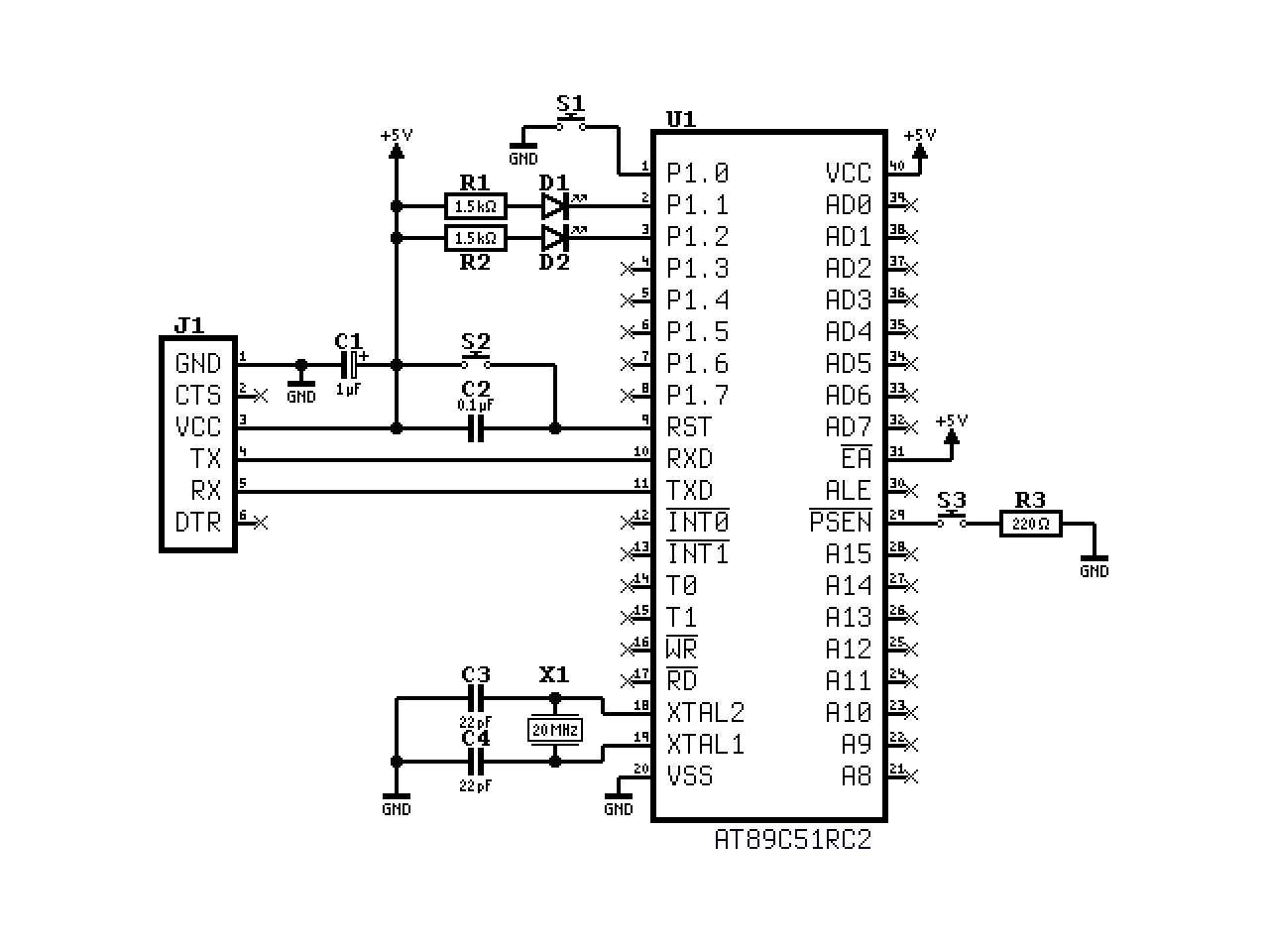
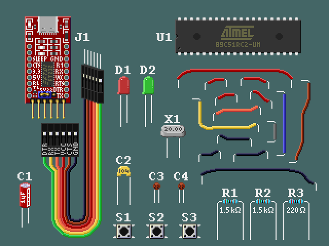
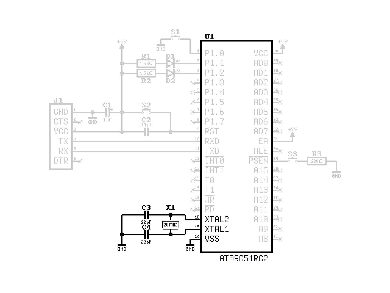
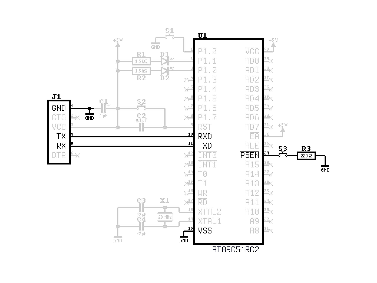
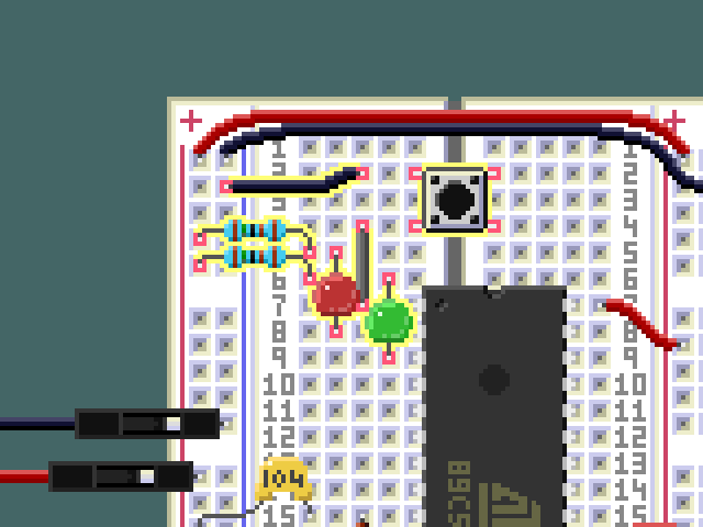
The schematic above shows the complete circuit. Besides the microcontroller itself, it can be divided into five blocks: power supply and decoupling, the crystal oscillator, the reset circuit, the serial interface, and finally some LEDs and a button for basic I/O. Each of these will be explained in detail later. A parts list can be found in the table below:
| Component | Value | Notes |
|---|---|---|
| U1 | AT89C51RC2 | Microcontroller |
| J1 | FT232 USB to UART | For programming and serial communication |
| S1 | Push button | General purpose input button |
| S2 | Push button | Reset button |
| S3 | Push button | Bootloader entry button |
| C1 | 1 µF | Decoupling capacitor |
| C2 | 100 nF | Power-on reset capacitor |
| C3, C4 | 22 pF | Load capacitors for the crystal |
| D1 | LED red | General purpose output LED |
| D2 | LED green | General purpose output LED |
| R1, R2 | 1.5 kΩ | Current limiting resistors for LEDs |
| R3 | 220 Ω | Series resistor for bootloader button |
| X1 | 20 MHz | Quartz crystal for the system clock |
| - | - | Breadboard and jumper wires |
Buying Components
All components can be bought from various online retailers or maybe even local electronics stores, if those still exist in your area. If you already have all the components, you can skip this section. If not, refer to the buying guide for my recommendations.
Buying Guide for the Components
- U1: AT89C51RC2-3CSUM
- The microcontroller itself is available from many sources, but I recommend buying it directly from the manufacturer or from a reputable supplier to avoid counterfeit chips. An overview of distributors can be found on Octopart. The part number should end in "-3CSUM", which stands for the 40-pin DIP package. That is important, as other packages won't work in a breadboard.
- J1: FT232 USB to UART Adapter
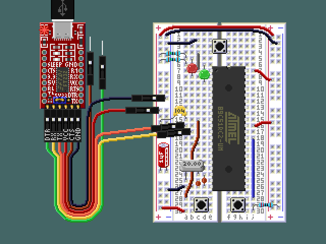
- For the USB to UART adapter, I recommend getting one with the FT232 chip, because that's what I tested with. It can be found on sites like Amazon or eBay. These adapters come in different shapes, sizes and colors, but any of them should work for this build as we only need the most basic signals: VCC, GND, TX, and RX. Some adapters plug directly into the USB port, while others have a cable. On the opposite side of the connection, most of them follow the pinout of the classic 6-pin FTDI cable (which you can also use, by the way). More on that later. Many come with so-called "Dupont wires", which are just jumper wires with pin headers. The ones I used have a female pin header on one end and a male pin on the other end. These are useful for connecting the adapter to the breadboard. This worked well for me here, but a setup where the adapter board is plugged into the breadboard directly, like shown in the illustration at the very beginning of this article, also works.
- S1-S3: Push Buttons
- Any small push button will work for the three buttons in this circuit. Instead of buying these separately, I recommend getting an "electronics starter kit" which will cover most of the remaining components as well.
- C1-C4: Capacitors
- These are most certainly included in any basic electronics kit. The values in this circuit are not critical, if you don't have the exact values specified, you can use similar ones. Anything between half and double the given value, or even slightly outside that range, will be fine.
- D1, D2: LEDs
- Again, these are included in most electronics kits. The color and size don't matter, and anything that comes in a kit should work. If you buy those separately, pay attention to the brightness rating. Some of them, mostly those with a clear lens, are blindingly bright even at normal current levels.
- R1-R3: Resistors
- These are also included in most electronics kits. The ones I looked at don't have the 1.5 kΩ resistors, but you can use 1 kΩ instead, which will just make the LEDs a bit brighter. You can also use larger value resistors to dim them. The 220 Ω resistor for the bootloader button is not critical at all, and can be anything between 100 Ω and 470 Ω.
- X1: Quartz Crystal
- You'll probably have to buy this separately, as it is not usually included in basic electronics kits. I recommend getting an assortment of crystals with different frequencies, as those are often not much more expensive than a single one and you get a nice box for free. If the assortment does not include 20 MHz, you can use a different frequency. I chose 20 MHz because that is the fastest speed the microcontroller can handle under any conditions. But since we don't use external memory, and are running at 5 V, you can go higher. If you prefer stability, go lower. "Odd" frequencies such as 14.7456 MHz or 22.1184 MHz are also a very good choice, because they are compatible with most baud rates, as will be discussed later.
- Breadboard and Jumper Wires
- A solderless breadboard and some jumper wires are needed to put everything together. These can be bought separately, but they are also included in most electronics kits. Some people swear by the original M3 breadboards, but so far I have found the cheaper alternatives to work just fine. For this project, one small breadboard with 30 rows will fit everything, if you connect the FTDI adapter via Dupont wires. (Those usually come with the adapter, the electronics kit, or maybe even both.) If you want to plug the adapter directly into the breadboard, you might need a larger one or use two small ones. That setup might also require soldering pin headers to the adapter.
The Microcontroller
The AT89C51RC2 is the star of the show. It is useful to get familiar with the datasheet. It contains all the information about the microcontroller, including the pinout, the internal architecture, and the peripheral features. For this project, we will only be using a small subset of the available features, but it is still good to have an overview of the whole thing. The microcontroller comes in a 40-pin DIP package, which is perfect for use on a breadboard.
The datasheet only briefly mentions the instruction set and standard 8051 peripheral features, as it assumes the reader is already familiar with them. They are explained in more detail in the 8051 Microcontrollers Hardware Manual.
I strongly recommend reading both documents all the way through, even if not everything (or anything at all) makes sense at first. When the time comes, you will remember that you have seen something about a certain feature or peripheral in the datasheet, and you can look it up again to refresh your memory.
With that said, it's time to start building!
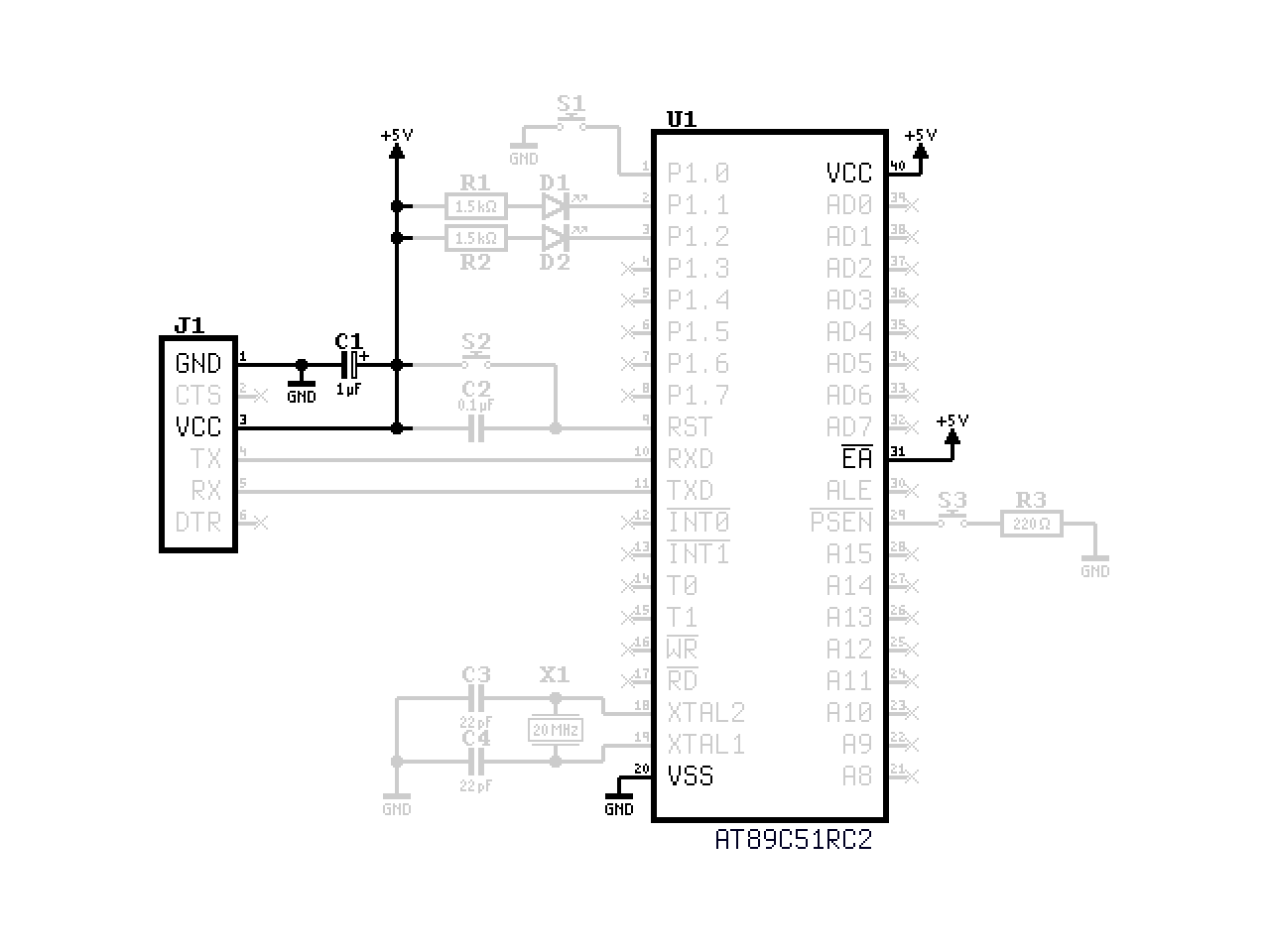
Power Supply and Decoupling
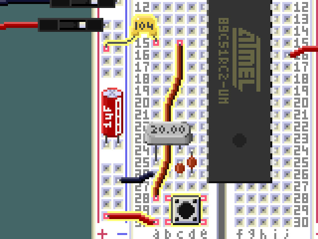
Power is supplied through the USB to UART adapter J1, which provides 5 V from the USB port. The VCC pin on J1 connects to the power rail on the breadboard, which in turn connects to the VCC pin of the microcontroller, and the ground pins are connected likewise. C1 is a 1 µF electrolytic decoupling capacitor placed between VCC and ground, to stabilize the power rail. The negative side of the capacitor is usually marked with a stripe and minus signs.
The serial adapter might have a jumper for selecting the output voltage. If it does, make sure to set it to 5 V. While 3.3 V should also work, it would just unnecessarily limit the performance and stability of the microcontroller.
If you prefer, you can also use a dedicated 5 V power supply. In that case, don't connect the VCC pin of the USB to UART adapter. (Although doing so, while not recommended, won't cause any damage in my experience.) Make sure to keep the grounds connected, however. Without the common ground, the serial communication will be very unreliable at best.
The EA pin is tied high to select internal program memory. This is not strictly necessary because, from the factory, external program memory is locked out through the lock bits in the hardware security byte. I prefer to do it anyway, just in case I grab a chip that is unlocked already.
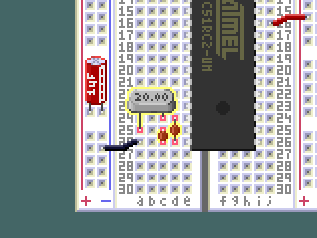
Crystal Oscillator
The 20 MHz quartz crystal X1 is connected to the XTAL1 and XTAL2 pins of the microcontroller. Two 22 pF load capacitors, C3 and C4, connect from each side of the crystal to ground. Together with the on-chip inverter, these components form a Pierce oscillator that provides the system clock.
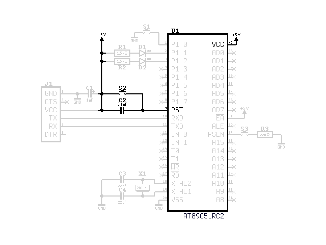
Reset Circuit
The RST pin is active high. C2 provides a power-on reset: when power is first applied, the capacitor is uncharged and briefly passes the supply voltage through to RST. The internal pull-down resistor then charges the capacitor, releasing the microcontroller from reset and allowing it to start running. S2 allows a manual reset at any time by momentarily connecting RST to VCC.
Serial Interface
The TX and RX lines of J1 are connected to the RXD and TXD pins of the microcontroller in a cross configuration. The transmitter of one side is connected to the receiver of the other side, and vice versa. This provides a serial link through the USB to UART adapter, which will be used both for programming the device and for communication at runtime.
The pinout of the USB to UART adapter seems to be fairly standardized between different manufacturers, making it easier to find compatible adapters. For reference, Table 2 shows the pinout of a typical adapter. The flow control signals (CTS and RTS) are not used in this project.
| Pin | Color | Signal | Description |
|---|---|---|---|
| 1 | Black | GND | Ground |
| 2 | Brown | CTS | "Clear To Send" flow control input |
| 3 | Red | VCC | Power supply |
| 4 | Orange | TX | Transmitted data output |
| 5 | Yellow | RX | Received data input |
| 6 | Green | RTS | "Request To Send" flow control output |
If tou look closely, you'll notice that the adapter I used deviates slightly from this standard pinout. It has DTR on pin 6 instead of RTS. We use neither of those signals, so it doesn't matter for our purposes. Just be aware that your adapter might have a different pinout. Some adapters also support additional modes (SPI, I2C, etc.), so make sure it is set to UART mode if necessary.
Pressing S3 pulls the PSEN pin low through R3. Holding it down during reset activates the built-in serial bootloader, which is how we will load our programs onto the chip.
LEDs and Button
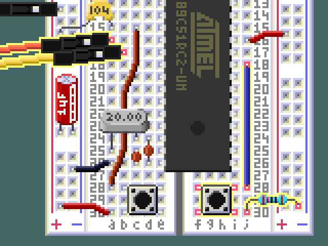
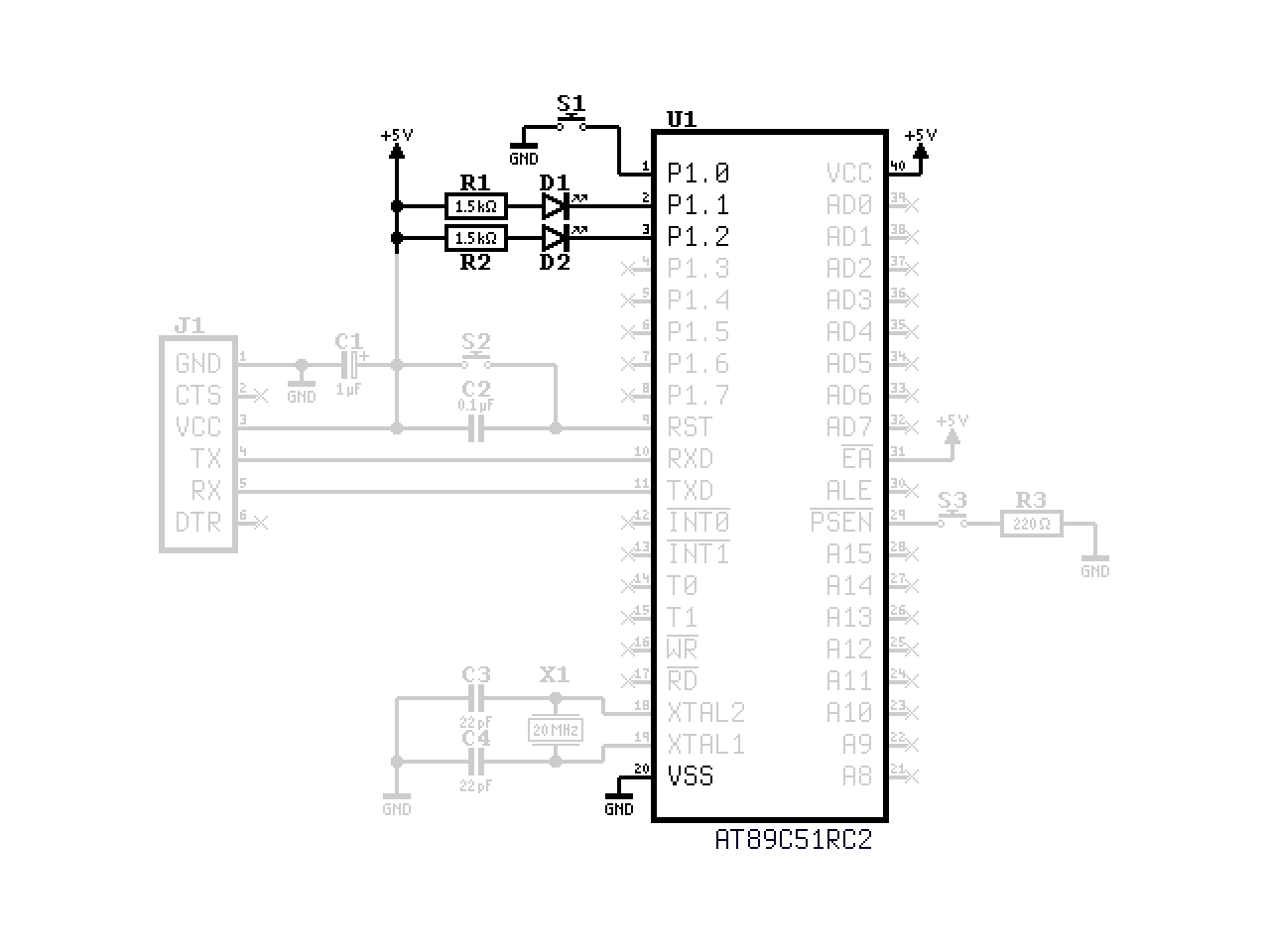
Two LEDs, D1 and D2, are wired from the +5 V rail through current limiting resistors R1 and R2 to port pins P1.1 and P1.2 respectively. Because they are connected to VCC on one end, they light up when the corresponding port pin is driven low. The polarity matters for correct operation. The longer lead of the LED is the anode (+), which is connected to the +5 V rail through a current limiting resistor. The shorter lead of the LED is the cathode (-), which is connected to the port pin of the microcontroller. You can also identify the cathode by the flat edge on the LED casing. In the schematic, it is the line the triangle points to.
Push button S1 connects P1.0 to ground and serves as a general purpose input. When the button is not pressed, the port pin reads high thanks to the internal pull-up resistor.
Finalizing the Build
At this point, the circuit is complete and ready to be powered on for the first time. Before you do that, double-check all your connections against the schematic and the breadboard images in this article. Make sure there are no accidental shorts, and that all components are in the right place. If you have a multimeter, you can use it to check for continuity and verify that the power supply is working correctly. Once you are confident that everything is set up correctly, you can proceed to power on the circuit. The result won't be very exciting at this point, because without a program, the microcontroller won't do anything.
If you have an oscilloscope, you can check the clock signal on the XTAL1 pin to verify that the crystal oscillator is working. If you don't have an oscilloscope, don't worry about it. As long as you followed the instructions correctly, it should work just fine.
Programming the Microcontroller
To program the microcontroller, we will use the built-in serial bootloader. A blank chip fresh from the factory comes with the BLJB (bootloader jump bit) fuse set to zero, so the bootloader starts automatically without pressing any buttons. (We will need the button later though, when we want to get back to the bootloader after running our own program.)
This leaves us with the task of setting up the other side of the serial connection. Below you can find a serial terminal that you can use to communicate with the bootloader. It uses the Web Serial API, which is supported by modern browsers such as Chrome and Edge. If you are using an Android device, the FT232 will probably not be detected through the Web Serial API. In that case, select the WebUSB FTDI driver instead.
After connecting, the bootloader expects you to send a capital letter "U" (which is "01010101" in binary) before sending anything else. This is used by it to detect the speed of the serial connection automatically. If it works, you will get the "U" echoed back from the bootloader and it will appear on the terminal. The baud rates for which this works depend on the crystal frequency. The default value of 9600 works with a wide range of them. A detailed table of supported baud rates by clock frequency can be found in the microcontroller's datasheet on page 98.
The Serial Terminal
This is the serial terminal that you can use to communicate with the bootloader. It will stay on top of the page as you scroll, so you can use it while reading the rest of the article. There is also a standalone version available that you can use for other purposes as well.
| Hex | Dec | Bin | Hex | Dec | Bin | |
|---|---|---|---|---|---|---|
| 0 | 0 | 0000 | 8 | 8 | 1000 | |
| 1 | 1 | 0001 | 9 | 9 | 1001 | |
| 2 | 2 | 0010 | A | 10 | 1010 | |
| 3 | 3 | 0011 | B | 11 | 1011 | |
| 4 | 4 | 0100 | C | 12 | 1100 | |
| 5 | 5 | 0101 | D | 13 | 1101 | |
| 6 | 6 | 0110 | E | 14 | 1110 | |
| 7 | 7 | 0111 | F | 15 | 1111 |
At the top there is a toolbar where you can select the driver, set the baud rate, and finally initiate a connection. Below that is the terminal window. You can focus it and type into it. When a connection is active, what you type will be sent over the serial link. There is no local echo, which means you won't see what you type unless there is something connected to the other end that responds.
There is also a text box where you can prepare your commands before sending them with the "Send" button. This is useful here, because the bootloader does not allow you to backspace or edit what you type, and if you make a mistake, you would have to start over when typing directly into the terminal. Using the text box makes the whole process much easier, especially for longer inputs.
Steps to Initiate Communication with the Bootloader
- Connect the USB to UART adapter to your computer or mobile device.
- Select the appropriate driver: Web Serial or WebUSB FTDI, depending on your device.
- Click or tap the "Connect" button in the serial terminal above and select the correct serial port.
- Press the reset button on the breadboard to start the bootloader.
- Type a capital "U" in the terminal window.
- If you see "U" appearing in the terminal, you are successfully connected to the bootloader and can proceed to the next section. If not, see the troubleshooting guide.
Troubleshooting Guide for Bootloader Connection Issues
If you are having trouble connecting to the bootloader, here are some things you can try to resolve the issue:
- Make sure you have selected the correct device. If the adapter has a TX LED, it should light up when you type something into the terminal. If you get connection errors or the device is not listed, try a different driver, different USB port, or a different cable. (Some USB cables are only for charging and do not support data transfer.) If the problem persists, try another computer or a different adapter.
- Perform a loopback test: Disconnect the adapter from the microcontroller and connect the TX and RX pins together directly. Then open a connection and type something into the terminal. If you see the characters appearing in the terminal, the adapter is working correctly. If not, try a different driver or baud rate. If the problem persists, try another adapter.
- Check the supply voltage on the microcontroller.
- After verifying the adapter works and the supply voltage is correct, check the connections on the breadboard. Make sure the TX and RX lines are going to their opposite counterparts on the microcontroller (TX goes to RX and vice versa), and that the ground is connected. Watch out for miscounted pin numbers. Write them onto the chip with a pencil to keep track.
- If you have an oscilloscope, you can use it to check if the oscillator is running by probing the XTAL pins. You can also use it to observe the signals on the TX and RX lines.
- If everything seems to be in order but it still doesn't work, challenge your base assumptions, keep checking everything, including issues you think are unrelated, and try to approach the problem from a different angle. Apply the scientific method. Repeat until you succeed. Don't give up!
Sending Commands to the Bootloader
The bootloader accepts commands in the form of Intel Hex records. It echoes but ignores all inputs before the start code (":") of a valid record. This means you can send other characters and they will appear on screen but be ignored. You can even enter notes or comments, and they won't have any effect, as long as you don't use the ":" character in them. I use this to start a new line after the initial "U" handshake, or when I want to start a new block of commands: Just hit enter and the cursor will move to the next line, keeping the terminal organized. Use the escape key followed by "c" to clear the terminal if it becomes too cluttered.
As soon as you begin a record with the ":" character, the bootloader will start interpreting the input as a valid Intel Hex record. At this point, no extra characters are allowed, even whitespace. Valid characters are the digits 0-9 and the letters A-F. Valid commands are acknowledged by the bootloader with a "." character, invalid ones with "X". You can try this out: type ":" followed by the number "8" eight times, and you should get an "X" in response. A terminal session could look like this:
[Press Connect to open a serial port.]
[Connecting...]
[Connected at 9600 baud.]
UUUUU
This text is ignored.
:88888888X
Now, let's move on to sending something that is actually valid.
Reading the Device ID
The first thing we can do once we are connected to the bootloader is to read the Device ID. This is a unique identifier that can be used to verify that we are communicating with the correct type of microcontroller. It is also a good exercise to get familiar with the process of sending commands to the bootloader and receiving responses.
The command for reading the first byte of the Device ID looks like this:
:020000050000F9Before we analyze how this command works, let's try it and see what happens. Connect to the microcontroller, perform the "U" handshake, and send the command. You can type it manually, or copy and paste it. In the terminal you should see this:
:020000050000F958.As you see, there are some extra characters at the end of the record that you didn't type. These are the bootloader's responses: a number, "58" in this case, followed by a "." indicating a valid command. "58" is the Manufacturer ID, which is byte zero of the Device ID that we just read.
Now let's find out how that command actually works. When the numbers are all written together like that, it is not easy to see what's going on. A tabular format can help visualize the components of the record.
| : | Len | Addr | Type | Data | Check |
|---|---|---|---|---|---|
| : | 02 | 0000 | 05 | 00 00 | F9 |
Now that the parts are separated into a table, it's easier to understand each component of the record:
- ":"
- Start code, indicates the beginning of a record.
- "02"
- Byte count, indicates the number of data bytes in the record. In this case, there are 2 data bytes.
- "0000"
- Address, indicates the memory address for the data. For this command, it is not used and set to 0000.
- "05"
- Record type, indicates the type of record. "05" is used for the "Read Function" of the bootloader.
- "00 00"
- Data, contains the data bytes for the command. In this case, it is the function code for reading the 0th byte of the Device ID, which is actually the Manufacturer ID.
- "F9"
- Checksum, used to verify the integrity of the record. It is calculated so that the sum of all bytes in the record, including the checksum, is zero.
Behind the serial terminal at the top of this page, there is another tab "IHexEditor", where you can edit Intel Hex records in a tabular format similar to the table above. It will calculate the length and checksum fields automatically and convert everything to the condensed format that you can directly copy and paste into the terminal. Page 104 of the microcontroller's datasheet has all the commands listed. Below are the commands for reading all four of the Device ID bytes:
| : | Len | Addr | Type | Data | Check | Description |
|---|---|---|---|---|---|---|
| : | 02 | 0000 | 05 | 00 00 | F9 | Manufacturer ID |
| : | 02 | 0000 | 05 | 00 01 | F8 | Device ID #1 |
| : | 02 | 0000 | 05 | 00 02 | F7 | Device ID #2 |
| : | 02 | 0000 | 05 | 00 03 | F6 | Device ID #3 |
Running the commands through the terminal should result in an output similar to this:
[Press Connect to open a serial port.]
[Connecting...]
[Connected at 9600 baud.]
U
:020000050000F958.
:020000050001F8D7.
:020000050002F7F7.
:020000050003F6EF.
You can try it out yourself to get familiar with the hex editor and the process of copying commands into the terminal, and also experiment with other commands from the datasheet if you like. If you do, compare the values you get with the description on page 89 of the datasheet. Otherwise, let's move on to the next part, where we will write a program in machine language like cavemen.
Writing a Simple Program
The program we will write uses the button and both LEDs in the most straightforward way possible:
- Turn on the red LED.
- Wait until the button is pressed.
- Turn off the red LED and turn on the green LED.
Here are the same steps visualized in a flowchart:
           Start
             │
             ▼
     ┌───────────────┐
     │    Turn On    │
     │    Red LED    │
     └───────┬───────┘
             │
             ├────────────┐
             │            │
             ▼            │
     ┌───────────────┐    │
     │   Is Button   │ No │
     │    Pressed?   ├────┘
     └───────┬───────┘
             │ Yes
             ▼
     ┌───────────────┐
     │   Turn Off    │
     │    Red LED    │
     └───────┬───────┘
             ▼
     ┌───────────────┐
     │    Turn On    │
     │   Green LED   │
     └───────┬───────┘
             │
             ▼
            End
Written descriptions and flowcharts are good for humans to understand the logic of a program, but the microcontroller doesn't understand them at all. It only understands machine code, which is a series of bytes that represent instructions and data. We will have to translate our program into machine code, using the instruction set of the 8051 architecture. Doing this manually is a tedious process, but it is a great way to learn how the microcontroller works at a low level. For a short program like this, it is not too bad, and maybe even fun.
I/O and Special Function Registers
The first step in the program should turn on the red LED. How does this work in practice? The link between the CPU, which executes our code, and the real world is through I/O ports and special function registers (SFRs). To the CPU those are just ordinary memory addresses, but they have special meanings and effects when accessed. Writing ones and zeroes there can make things happen, like turning on an LED or reading the state of a button.
The LEDs and the button are connected to Port 1. The corresponding SFR for Port 1 is P1. It can be found in Table 5 on page 5 in the datasheet. There it tells us that the corresponding address is "90h". The "h" stands for "hexadecimal". Another common way to write hex numbers would be "0x90", which means the same and is what I prefer to use when writing code. If we look up that address in the table on page 8, we can see that the default value is "1111 1111". This means that all the pins of Port 1 are initially set to high, which corresponds to the LEDs being off, because we wired them to turn on when the pin is low. (This was done on purpose, because the microcontroller's current limits for "sinking" current are less strict than for "sourcing" current, and also the LEDs start in the "off" state by default.)
The First Instruction
What we have learned so far is that the LED is controlled by a bit in a register that lives at address 0x90, and that it contains a 1 by default which we need to replace with a 0 to turn on the LED. Which instruction do we need to achieve this? A good place to look is the Instruction Set Summary on page 1-15 of the 8051 Hardware Manual. It spans only four and a half pages, so it's not too overwhelming. The instruction that seems to be made for what we are trying to do lives in the "Boolean Variable Manipulation" section and is called "CLR bit - Clear direct bit".
The details on the instruction are on page 1-31. There is even an example very similar to what we are trying to do. Below the example there are two variants, of which the second one is the one we need. It looks like this:
CLR bit
───────

    Bytes: 2
   Cycles: 1

           ┌───────┬───────┐ ┌─────────────┐
 Encoding: │1 1 0 0│0 0 1 0│ │ bit address │
           └───────┴───────┘ └─────────────┘

Operation: CLR
           (bit) ← 0
This tells us that we need two bytes to encode this instruction. The first one is straightforward, it is always "1100 0010", which in hexadecimal is 0xC2. The second one is a bit more mysterious, because it depends on the "bit address" of the bit we want to change. What is a bit address? The manual has a section on Boolean Instructions, but it doesn't explain the actual encoding of the bit address. Luckily, it is pretty straightforward. The important thing to know is that bit addressing only works for specific memory addresses, specifically those where the three least significant bits are zero (and therefore the address is a multiple of 8). The reason for this is that those three binary digits of the address are where the number of the bit (0-7) goes. The rest of the bits in the address are used to select the byte that contains the bit to be cleared. For our case, where the LED is connected to P1.1, we need to combine the address of the P1 SFR (0x90) with the bit number (1) to get the bit address (0x91).
This gives us the first instruction for our program, which so far looks like this:
| Label | Address | Instruction | Operands | Machine Code |
|---|---|---|---|---|
| start: | 0x0000 | CLR | P1.1 | C2 91 |
Waiting for the Button Press
The button lives right next to the LED on P1.0. When it is pressed, it will pull the pin low, which we can detect in our program by reading the bit from the SFR. The flowchart shows a decision point where there are two possible ways the program can go. The branch that diverts from the path straight through is the one where the button is not pressed. It loops back right to checking the button state again. Such diversions are handled by a conditional jump instruction. The one we need can be found not far from the CLR instruction we just used, in the Boolean Instructions section of the manual: JB bit,rel
This instruction stands for "Jump if Bit". It checks the value of the specified bit, and if it is set (i.e. if it is one), it jumps to the specified relative address. If the bit is not set, it continues with the next instruction in sequence instead. Here is what it looks like in the manual on page 1-40:
JB bit,rel
──────────

    Bytes: 3
   Cycles: 2

           ┌───────┬───────┐ ┌──────────┐ ┌──────────┐
 Encoding: │0 0 1 0│0 0 0 0│ │ bit addr │ │ rel addr │
           └───────┴───────┘ └──────────┘ └──────────┘

Operation: JB
           (PC) ← (PC) + 3
           IF (bit) = 1
              THEN (PC) ← (PC) + rel
This instruction needs three bytes to encode. The first two bytes work similarly to the CLR instruction, but the third one is new. It tells the CPU where to go if the condition is met, which in our case is a button that is not pressed. Remember: the pin is high by default, pressing the button pulls it low. The relative address is a number that counts how many bytes to jump forward or backward. This jump happens after the program counter (PC) has already been increased by 3 and points to the next instruction. This means that if we want to jump back to the JB instruction itself, we need to set the relative address to -3, which is 0xFD in two's complement.
To put everything together, we take the first byte for the JB instruction (0x20), the bit address for P1.0 (0x90), and the relative address (0xFD) to form the complete instruction. Together with the instruction we already had, our program now looks like this:
| Label | Address | Instruction | Operands | Machine Code |
|---|---|---|---|---|
| start: | 0x0000 | CLR | P1.1 | C2 91 |
| loop: | 0x0002 | JB | P1.0,loop | 20 90 FD |
Off and On Again
Now we are halfway there. Our plan calls for another instruction to turn the red LED off. This is done by the SETB instruction which is the opposite of the CLR instruction we used earlier. It looks like this:
SETB bit
────────

    Bytes: 2
   Cycles: 1

           ┌───────┬───────┐ ┌─────────────┐
 Encoding: │1 1 0 1│0 0 1 0│ │ bit address │
           └───────┴───────┘ └─────────────┘

Operation: SETB
           (bit) ← 1
The instruction for turning on the green LED is another CLR instruction, but this time for P1.2 instead of P1.1. Putting everything together, we get the (almost) complete program:
| Label | Address | Instruction | Operands | Machine Code |
|---|---|---|---|---|
| start: | 0x0000 | CLR | P1.1 | C2 91 |
| loop: | 0x0002 | JB | P1.0,loop | 20 90 FD |
| 0x0005 | SETB | P1.1 | D2 91 | |
| 0x0007 | CLR | P1.2 | C2 92 |
Halt, Stop!
We are not done yet, because after turning on the green LED, the program will just continue executing whatever is next in memory, which is not good. We need to add an instruction at the end to stop the program from doing anything else. The 8051 instruction set does not have a proper "halt" instruction, but we can achieve the same effect by jumping to the same address indefinitely. The instruction for an unconditional jump is "SJMP rel", which stands for "Short Jump". It is similar to the JB instruction we used earlier, but without the condition. It looks like this:
SJMP rel
────────

     Bytes: 2
    Cycles: 2

            ┌───────┬───────┐ ┌─────────────┐
  Encoding: │1 0 0 0│0 0 0 0│ │ rel address │
            └───────┴───────┘ └─────────────┘

Operation: SJMP
           (PC) ← (PC) + 2
           (PC) ← (PC) + rel
SJMP is only two bytes long. To jump to the same address, we need to set the relative address to -2, which is 0xFE in two's complement. Adding this instruction to the end of our program gives us the final version:
| Label | Address | Instruction | Operands | Machine Code |
|---|---|---|---|---|
| start: | 0x0000 | CLR | P1.1 | C2 91 |
| loop: | 0x0002 | JB | P1.0,loop | 20 90 FD |
| 0x0005 | SETB | P1.1 | D2 91 | |
| 0x0007 | CLR | P1.2 | C2 92 | |
| end: | 0x0009 | SJMP | end | 80 FE |
With that, the tedious process of writing machine code by hand is complete. There are two more hurdles to overcome before we can finally see some LEDs light up and react to button presses. Exciting, isn't it? Well, the real excitement will come when you realize that using the same principles, anything can be built, and you are only limited by your imagination and willingness to learn and experiment. So without further ado, let's move on to the final steps of getting our program onto the microcontroller and running it.
Loading and Running the Program
To load our program into the microcontroller, we need to convert it into the Intel Hex format we already experimented with earlier. Writing program memory is done with records of type "00". Usually each record contains a fixed amount of data, often 16 bytes, so our program would fit into a single record. For readability, I will use one record per instruction instead, which the bootloader will accept just fine.
Using the IHexEditor, the program can be converted to Intel Hex format like this:
| : | Len | Addr | Type | Data | Check |
|---|---|---|---|---|---|
| : | 02 | 0000 | 00 | C2 91 | AB |
| : | 03 | 0002 | 00 | 20 90 FD | 4E |
| : | 02 | 0005 | 00 | D2 91 | 96 |
| : | 02 | 0007 | 00 | C2 92 | A3 |
| : | 02 | 0009 | 00 | 80 FE | 77 |
[Press Connect to open a serial port.]
[Connecting...]
[Connected at 9600 baud.]
U
:02000000C291AB.
:030002002090FD4E.
:02000500D29196.
:02000700C292A3.
:0200090080FE77.
The bootloader responds with a "." for each valid record. The program is now stored in the program memory of the microcontroller, but there is one last thing we have to do before we can finally run it.
Setting the Boot Loader Jump Bit
Right now, hitting the reset button lands us right back at the bootloader instead of running the program we just loaded into memory. To change that, we have to set the boot loader jump bit. This will configure the microcontroller to run the program stored in its memory instead of the bootloader. The command to do this can be found on page 104 of the datasheet, and it looks like this:
| : | Len | Addr | Type | Data | Check |
|---|---|---|---|---|---|
| : | 03 | 0000 | 03 | 0A 04 01 | EB |
:030000030A0401EBAfter sending this command, the BLJB fuse will be set and the microcontroller will run the program stored in its memory as soon as it is reset. Don't worry, there is a way to get back to the bootloader if needed (that's what the button on the PSEN line is for), so go ahead and press that reset button. If everything went to plan, the red LED should light up. If you then press the input button, the red LED should turn off, and the green LED should turn on.
Congratulations! You have now successfully loaded and run your first program on the 8051 microcontroller. If instead it didn't work as expected, you'll need to troubleshoot. For this you'll have to go back to the bootloader and inspect program memory. Luckily the next section covers this anyway, so you can just continue reading, and try again after you have learned how to read program memory and verify that the program is actually there and correct.
Reading and Erasing Program Memory
To get back to the bootloader with the BLJB fuse set, follow these steps:
- Press and hold the RESET button
- Press and hold the button on the PSEN line
- Release the RESET button
- Release the button on the PSEN line
After this, the bootloader will be active again, waiting for you to send "U" over the serial link.
Reading Program Memory
The bootloader has a command for reading program memory, which is similar to the command for reading the Device ID that we used earlier. Again, the address field is not used. Instead, the data field contains the start and end addresses for the block of memory to be read. Command type 04 is used for this purpose. Details can be found on page 104 of the datasheet.
| : | Len | Addr | Type | Data | Check |
|---|---|---|---|---|---|
| : | 05 | 0000 | 04 | 00 00 00 7f 00 | 78 |
:050000040000007F0078The bootloader will respond with something that looks like this:
0000=C2912090FDD291C29280FEFFFFFFFFFF
0010=FFFFFFFFFFFFFFFFFFFFFFFFFFFFFFFF
0020=FFFFFFFFFFFFFFFFFFFFFFFFFFFFFFFF
0030=FFFFFFFFFFFFFFFFFFFFFFFFFFFFFFFF
0040=FFFFFFFFFFFFFFFFFFFFFFFFFFFFFFFF
0050=FFFFFFFFFFFFFFFFFFFFFFFFFFFFFFFF
0060=FFFFFFFFFFFFFFFFFFFFFFFFFFFFFFFF
0070=FFFFFFFFFFFFFFFFFFFFFFFFFFFFFFFF
The first line contains the data we just wrote into memory, and the rest is just empty memory filled with 0xFF. If you see anything else in there or you want to start again from a clean slate, you can perform a full chip erase with this command:
| : | Len | Addr | Type | Data | Check |
|---|---|---|---|---|---|
| : | 01 | 0000 | 03 | 07 | F5 |
This command takes about six seconds to execute before the bootloader will respond with a ".". Note that it is not necessary to erase memory every time you load a new program. When overwriting existing data, the bootloader will automatically handle the necessary erasure. Portions of memory that are not overwritten will contain whatever is left from the previous program, though. In this situation, a full chip erase can help clean things up and avoid cluttered memory.
A Slightly More Interesting Program
The program so far is of questionable utility. You press a button, and a red light becomes green. Not very useful, except maybe at a pedestrian crossing. With a few modifications, however, we can turn it into something arguably more useful.
This time around, however, let's do things in reverse. Starting with the modified code, let's figure out what it does:
| Label | Address | Instruction | Operands | Machine Code |
|---|---|---|---|---|
| start: | 0x0000 | CLR | P1.1 | C2 91 |
| loop: | 0x0002 | JB | P1.0,loop | 20 90 FD |
| 0x0005 | XRL | P1,#0b00000110 | 63 90 06 | |
| 0x0008 | SJMP | loop | 80 F8 |
The first two lines are the same as before: Turn on the red LED and wait for a button press. The third line is new. It uses the XRL instruction to do the same thing we needed two instructions for before. It turns off the red LED and turns on the green LED. It does this by performing a bitwise exclusive OR (XOR) operation between the current value of Port 1 and the constant 0b00000110. The XOR operation will flip the bits in Port 1 that correspond to the ones in the constant, which in this case belong to the pins with the LEDs.
The last line is also new. Instead of ending the program, it jumps back to the loop label, creating an infinite loop that continuously checks the button and toggles the LEDs. As long as the button is held down, the LEDs will keep toggling back and forth between red and green. When you release the button, the LEDs will stop toggling, but which one will be on then? It depends on the last state before the button was released, which at this speed is essentially random. We have created an electronic coin toss simulator.
Exercises
Before we wrap up, here are some fun things to try:
- Convert the coin toss program to Intel Hex format and try it on your 8051 microcontroller. Does it work as expected?
- Do you think the coin is "fair", i.e. does it have an equal chance of landing on heads or tails (red or green)? Conduct an experiment to test your hypothesis!
- What can you do to change the probability of landing on heads or tails?
- How about adding a third LED?
Hints
When I first tried the program, the result surprised me. It does not behave like a fair coin toss. For me it landed on green far more often than on red, so if you see this behavior, don't be alarmed.
Why is that, though? The reason has nothing to do with the code, but with electrical noise and the way the microcontroller samples the button. When you release the button, the internal pull-up resistor will be responsible for restoring the high level on the pin, which takes some time. At some point a threshold will be crossed and the microcontroller will register the button as "not pressed" anymore. It seems like having the neighboring pin on a high state (red LED off) will cause the threshold to be crossed sooner, which makes the program more likely to stop on green.
The behavior might even differ between different chips and also depend on environmental factors such as temperature and electromagnetic interference. A more robust approach is needed. Try different strategies and find out what works reliably, for example:
- Swapping pins 0 and 1, so that the button is between the LEDs.
- Moving the LEDs to port pins further away from the button or using separate ports.
- Adding a delay in the program at a strategic point.
- Using the carry flag to flip between heads and tails while the button is pressed, so that the LEDs can be off entirely during that time.
As you might have noticed, complexity suddenly exploded. Even a program that only consists of four instructions can lead you down a rabbit hole of puzzles to solve. Some of the solutions warrant more powerful tools, as assembling code by hand becomes impractical. See the end of this article for more information.
Conclusion
In this article, we built a working 8051 microcontroller system from scratch using only a handful of components on a solderless breadboard. We connected a crystal oscillator, a reset circuit, a serial interface, and some LEDs and a button for basic I/O. We then used the built-in serial bootloader to communicate with the microcontroller through a web-based serial terminal, read the Device ID, and write programs directly in machine code. Along the way, we learned how instructions are encoded, how bit addressing works, and how to translate a simple idea into bytes that the processor can execute.
Where to Go From Here
For more complex programs you'll need an assembler, which automates the translation of assembly code into machine code. I have found as31 to work adequately. If you are on Linux, it can probably be installed through your package manager. Binaries for other platforms are available at PJRC. I am currently working on an online version, which I will link here as soon as it is ready. Meanwhile you can also try the other software from that PJRC page. If you get PAULMON2 running on the AT89C51, let me know. I haven't tried it myself yet. Of course, there are also C compilers for the 8051 available. SDCC is a good choice in my opinion.
I hope you enjoyed this rather unusual journey into the world of microcontrollers. Instead of using the established tools and workflows, we went down to the very basics and did everything by hand, from wiring the circuit to writing machine code. This approach is not the most efficient, but I hope it gave you a deeper understanding of how microcontrollers work, and a baseline to go back to when things suddenly stop making sense with the more complex tools. Nothing can stop you now, so have fun!
Acknowledgements
- This article is licensed under the Creative Commons Attribution 4.0 International License (CC-BY-4.0).
- The Serial Terminal code embedded in this document is licensed under the MIT License.
- xterm.js and @xterm/addon-fit are used under the MIT License.
- WebUSB FTDI driver is used under GPL-2.0.